
Professional Engineering Resources
Comprehensive Library of Software, Calculators & Technical Knowledge
Free engineering calculators, licensed desktop software, and in-depth technical articles — built for engineers who need fast, code-compliant answers without re-deriving formulas from scratch. Coverage includes ASME Section VIII Div.1 & Div.2 pressure vessel design, AISC 360 structural steel and connection design, WRC Bulletin 537. Built by Fayaz Memon, a Lead Mechanical Engineer with 19 years of experience in pressure vessel design, structural analysis, and API oil storage tank engineering across Saudi Arabia's oil & gas industry. That background in pressure vessel and structural engineering is paired with professional .NET software development. Each calculator on this site applies the same code requirements and calculation methods used in day-to-day project work, and the licensed software titles — including nozzle stress analysis and 3D modeling tools — were built using that same engineering knowledge.
Professional Software Suite
Licensed desktop software — each title sold on its own annual subscription, no site membership required
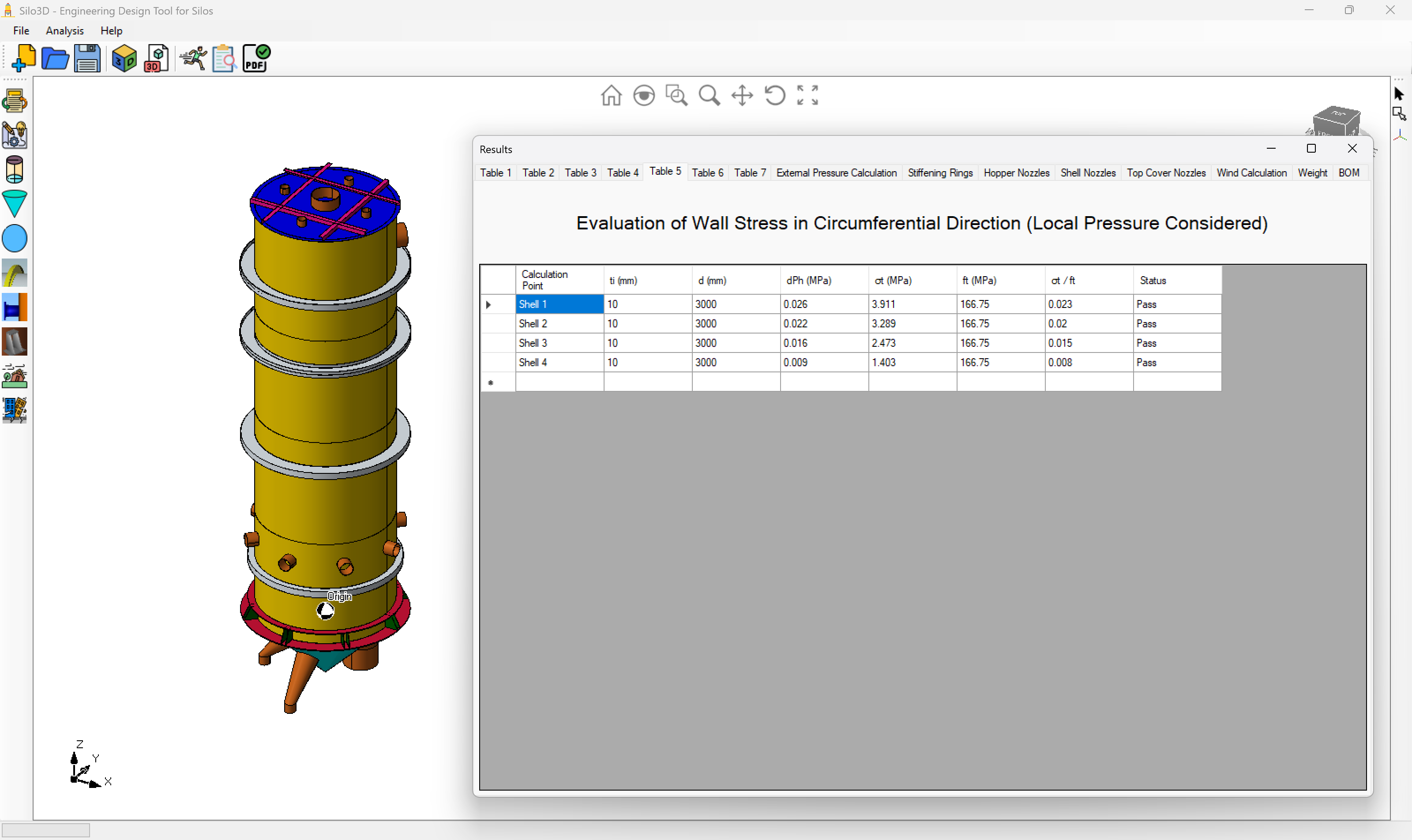
Silo3D
Comprehensive silo design and analysis tool with 3D visualization. Handles bulk material properties, flow patterns, structural calculations, and foundation design.
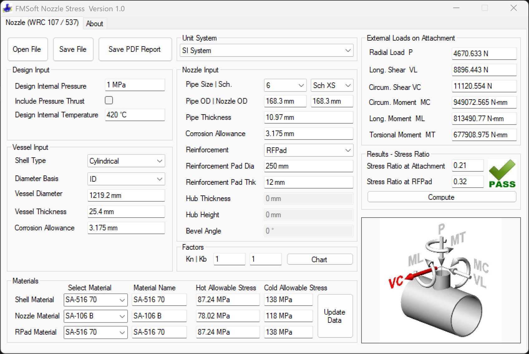
Nozzle Stress Analysis Software
Calculate stresses in cylindrical and spherical shells at nozzle junctions per WRC Bulletin 537/107. Handles external loadings and reinforcement pad analysis.
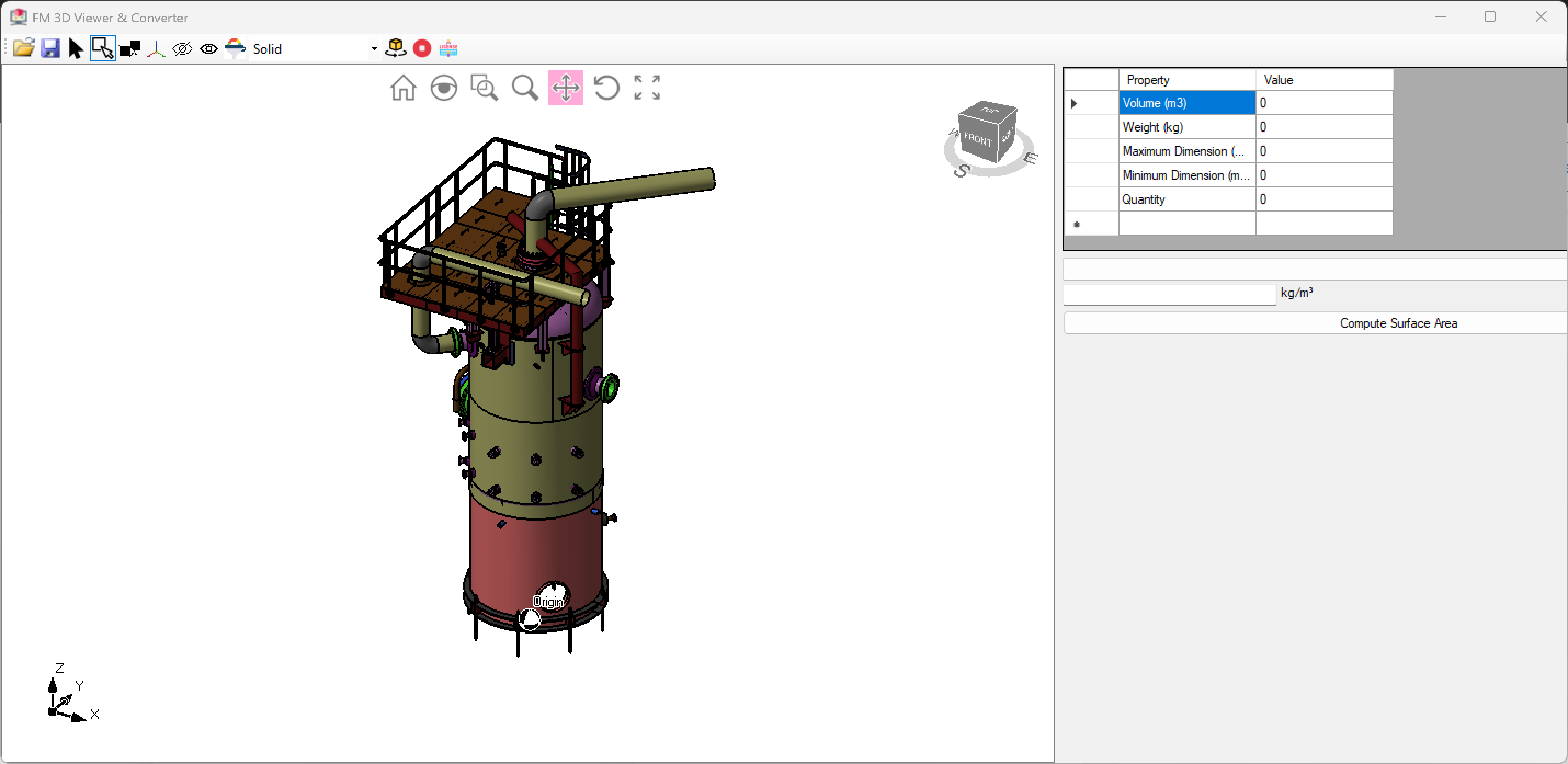
FM 3D Model Viewer
Windows application for viewing and converting 3D files. Calculate volumes, weights, surface areas with material density database and measurement tools.
Professional Calculators
Specialized engineering calculators — free tools with no account required
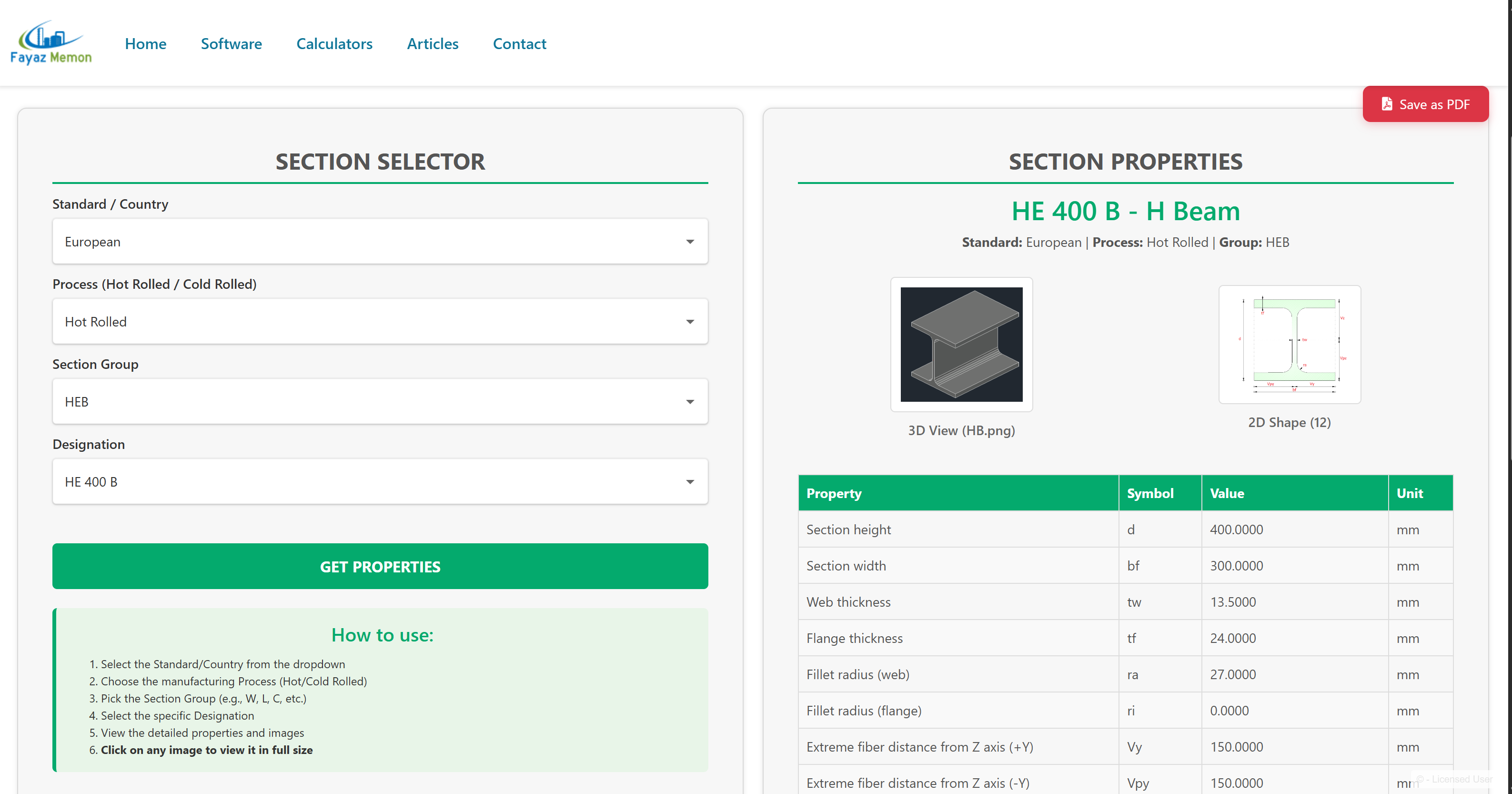
Standard Steel Sections
Standard dimensions and properties for more than 25,000+ structural steel sections (profiles) from various countries.
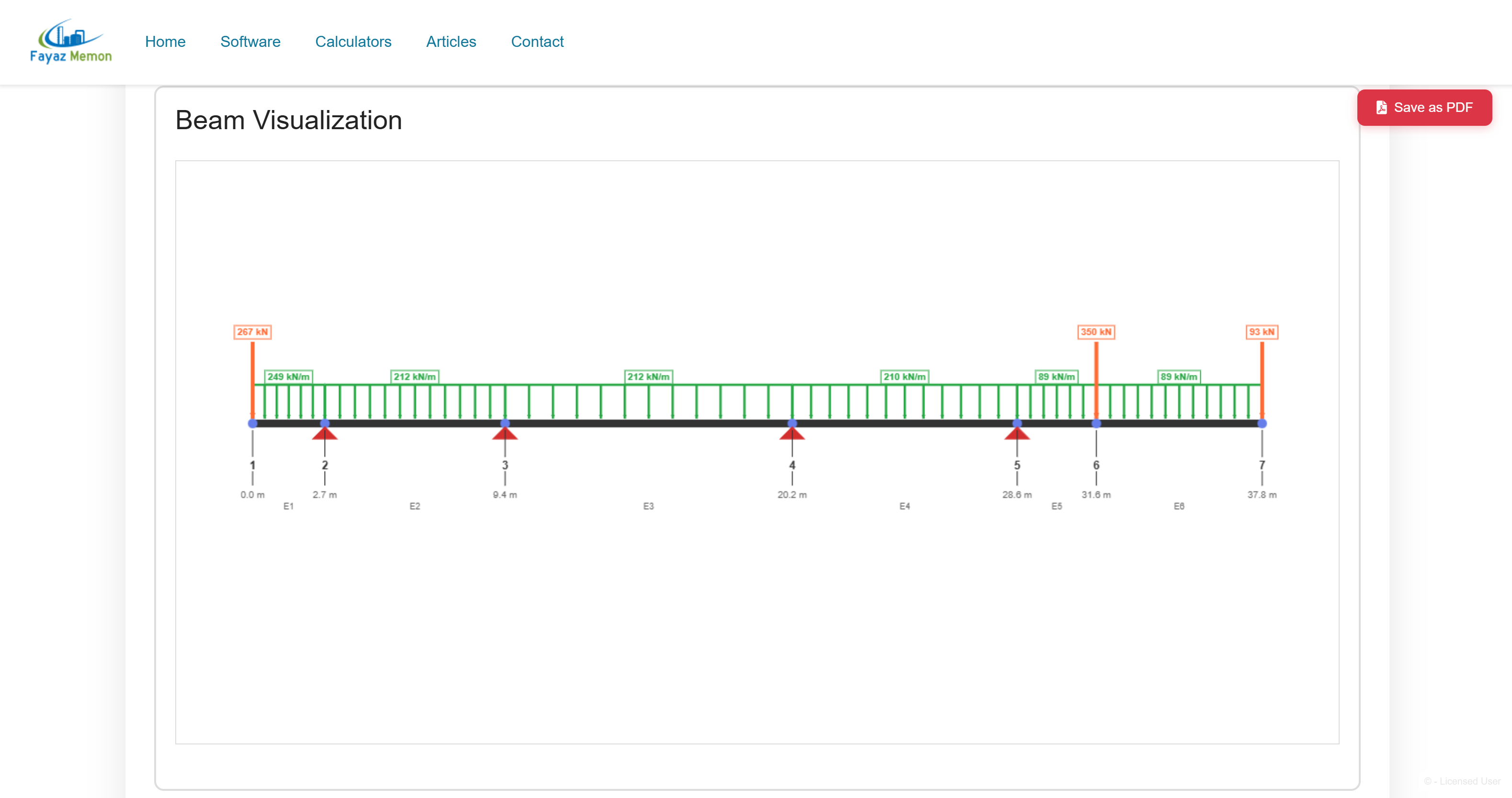
Beam Analysis Tool
Finite Element Method (FEM) analysis for beams with point loads, distributed loads, and multiple support types. Generates shear force and bending moment diagrams instantly.
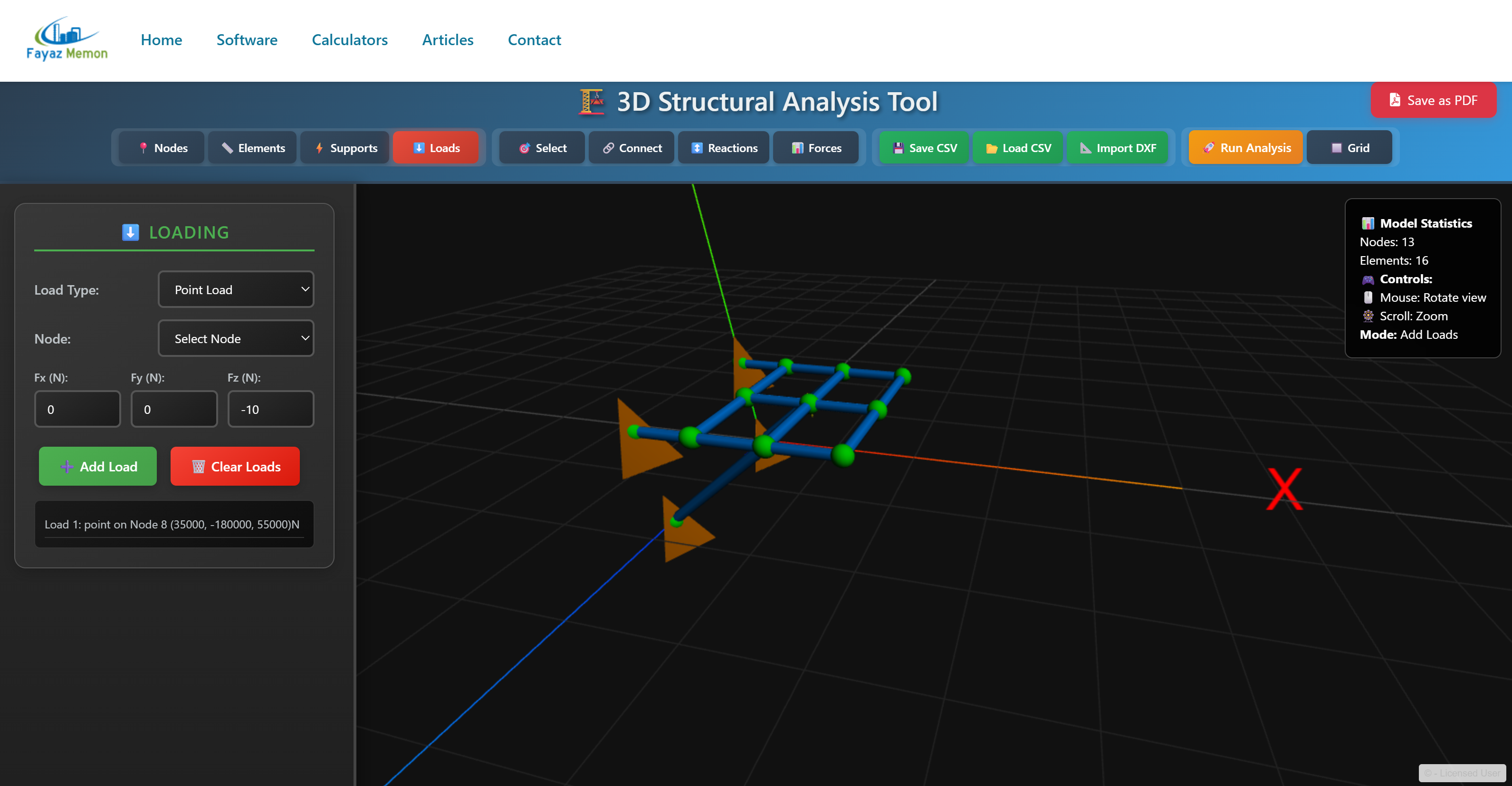
3D Structure Analysis Tool
Browser-based FEA for trusses and frames with full 6-DOF analysis. Import AutoCAD DXF files, model complex structures, and generate engineering reports.
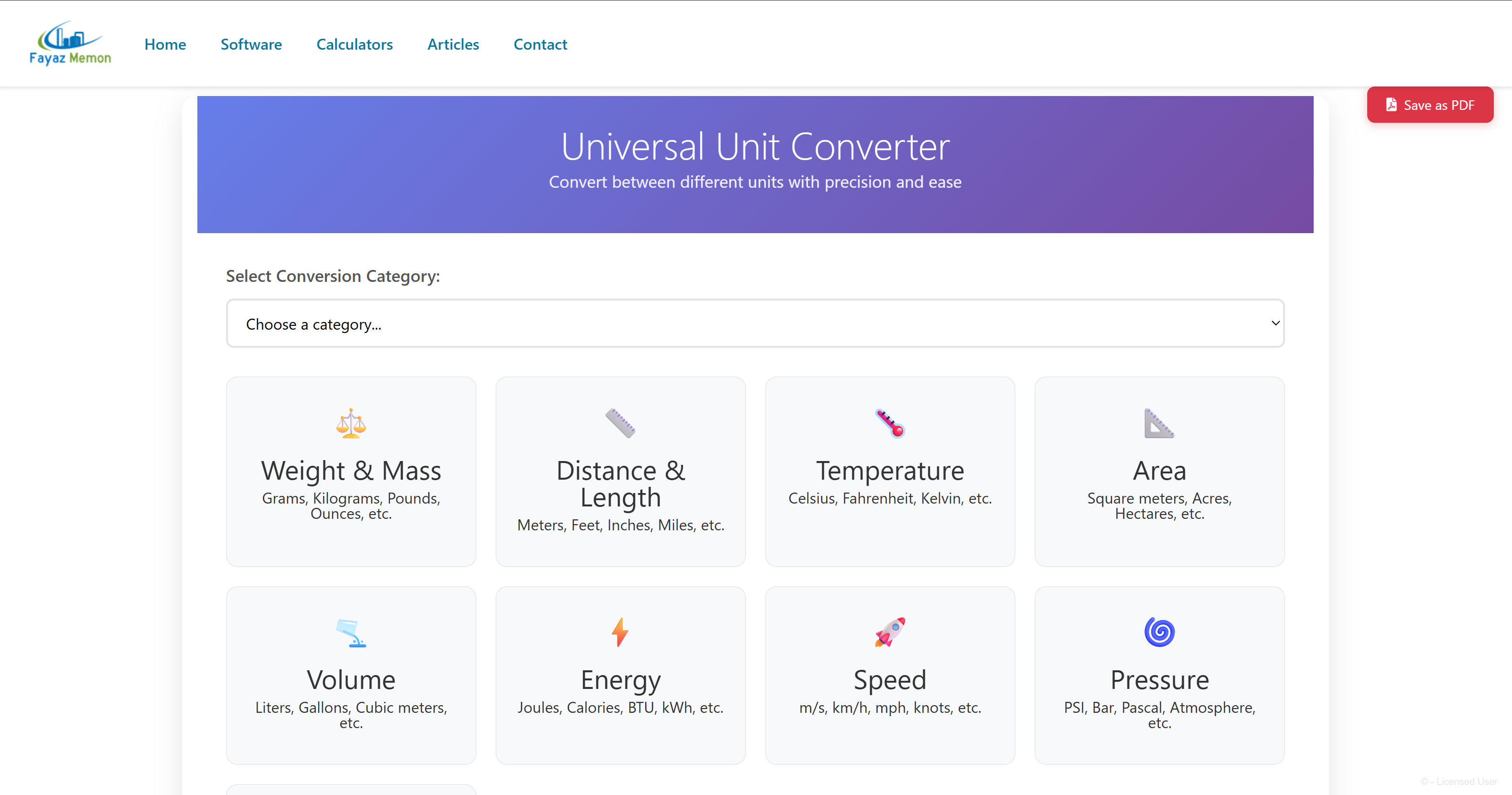
Universal Unit Converter
Convert between 150+ units across 18 categories — weight, length, temperature, area, volume, pressure, force, and more — with instant precision.
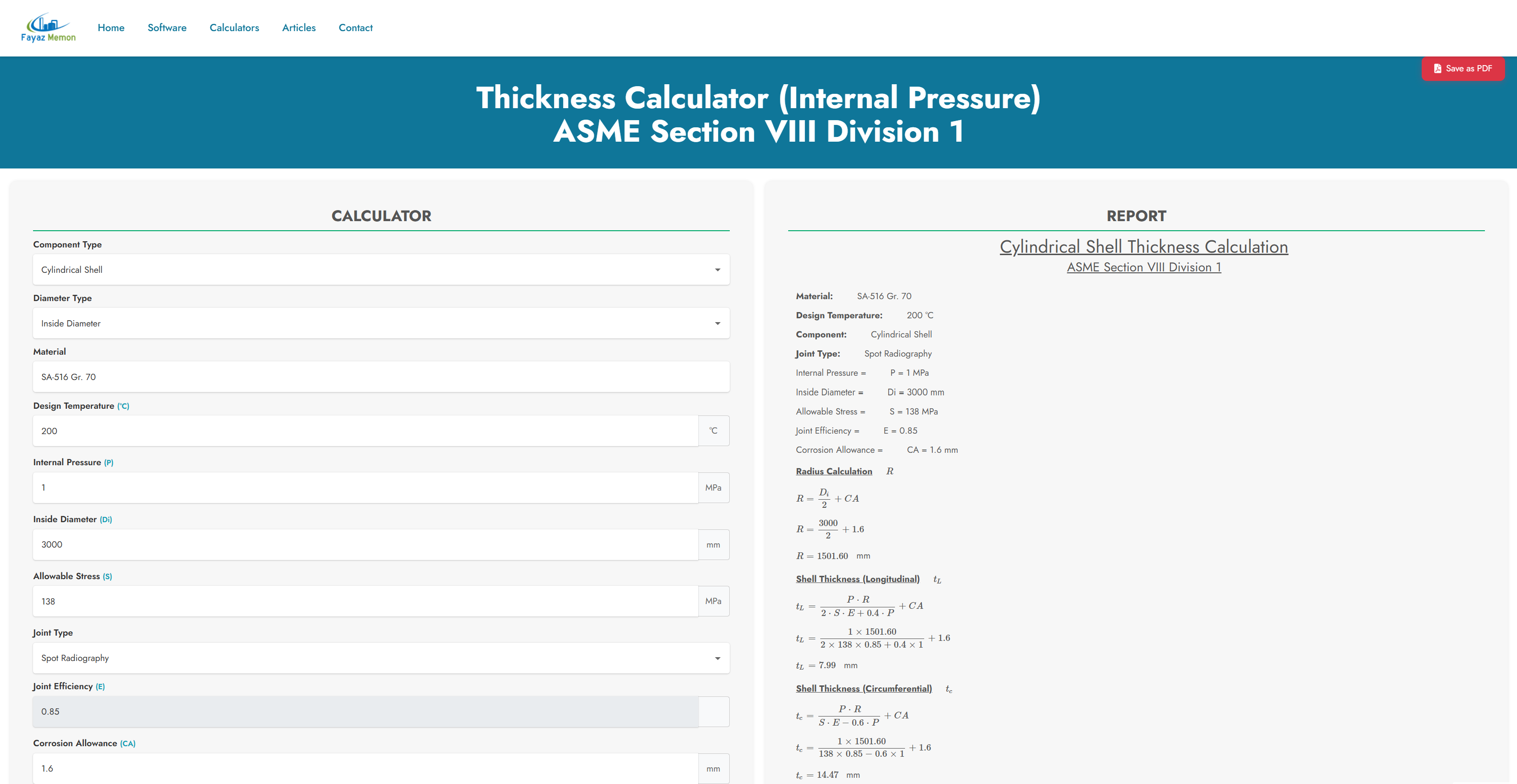
Thickness Calculator (ASME VIII Div.1)
Calculate minimum required thickness for cylindrical shells, spherical shells, and formed heads under internal pressure per ASME Section VIII Division 1.
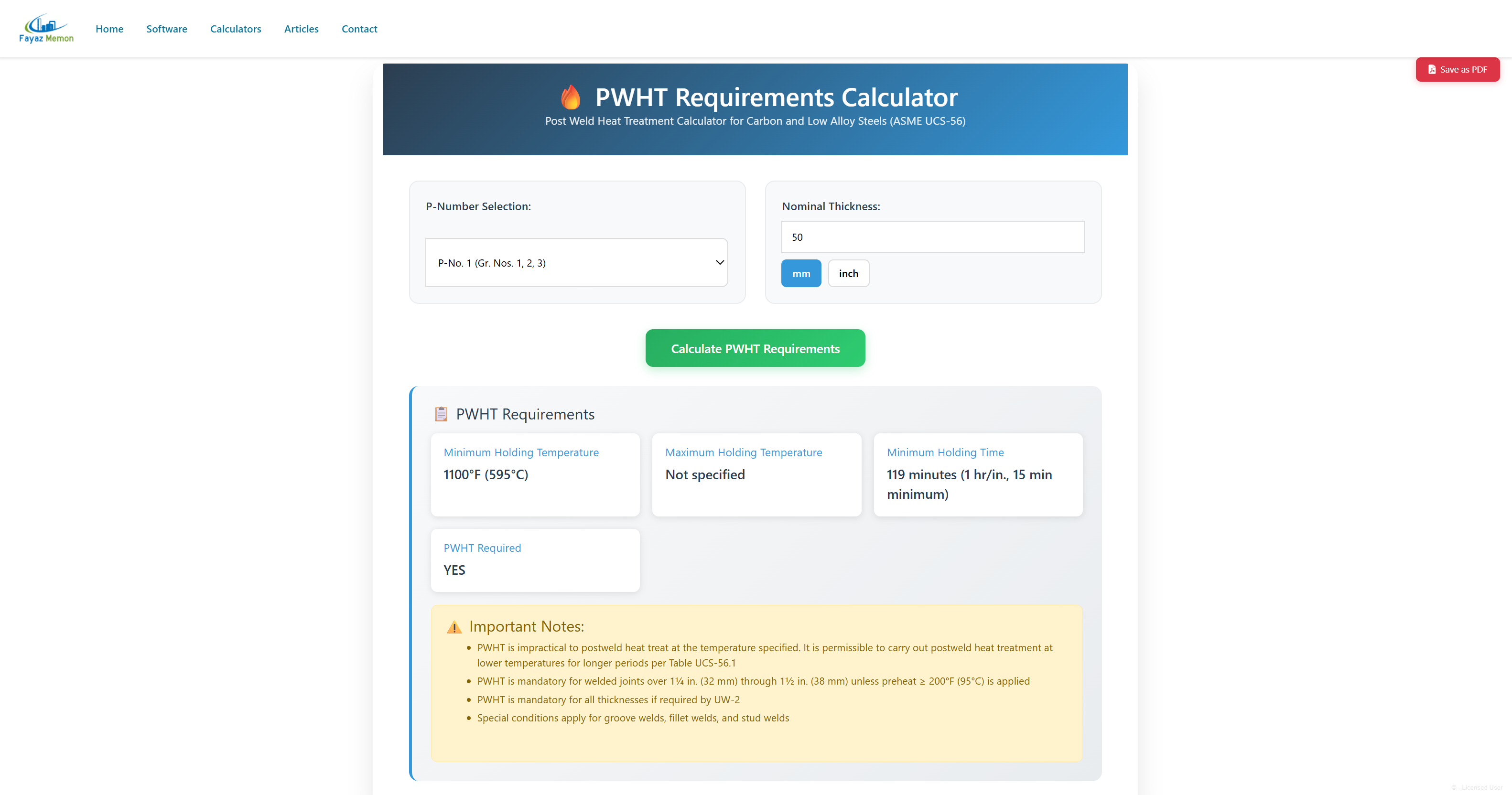
PWHT Requirement
Evaluate post-weld heat treatment requirements based on material type and thickness according to ASME Section VIII Division 1.
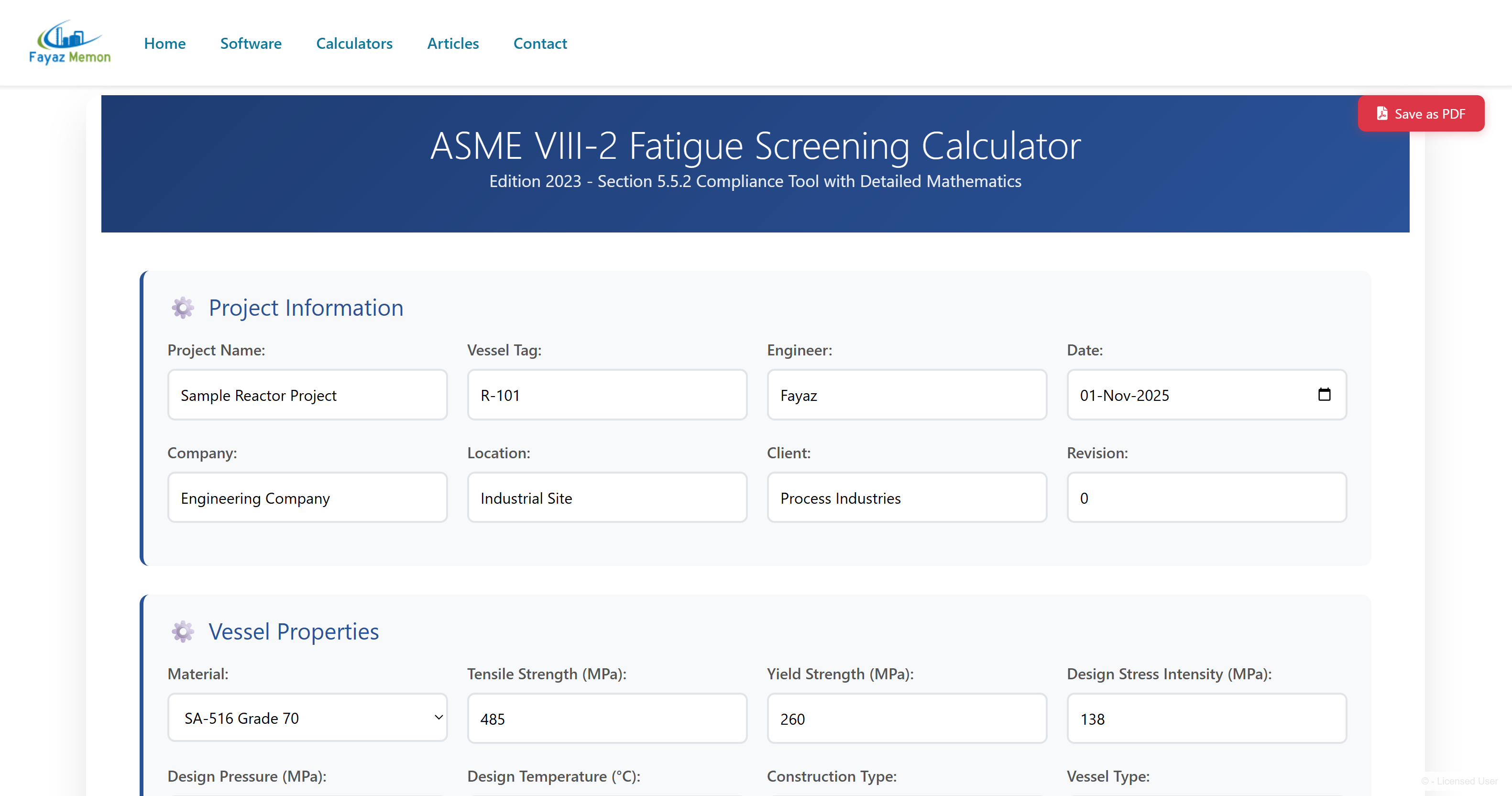
Fatigue Screening (ASME VIII Div.2)
Fatigue assessment screening criteria to determine if detailed fatigue analysis is required for cyclic loading conditions.
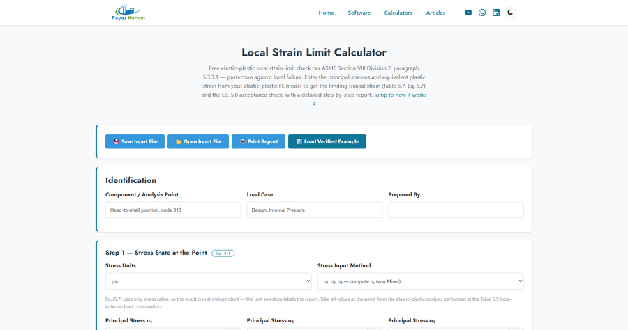
Local Strain Limit (ASME VIII Div.2)
Elastic–plastic protection against local failure per 5.3.3.1 — Table 5.7 limiting triaxial strain and Eq. 5.8 acceptance check with a step-by-step report.
Technical Articles & Knowledge Base
In-depth engineering insights, tutorials, and best practices
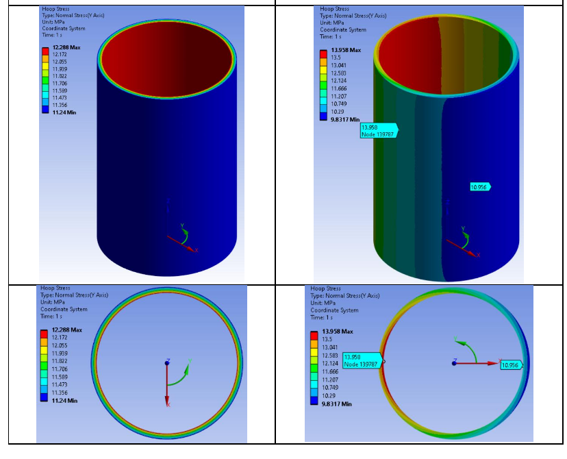
Understanding the Importance of Minimum Wall Thickness in Nozzle Stress Analysis
A comprehensive guide examining the critical decision between using nominal vs. minimum wall thickness in nozzle-to-shell junction analysis, with detailed WRC 537/297 perspectives and practical examples.
Key Topics Covered:
- ASME BPVC Section VIII Division 2 requirements
- WRC 537 and WRC 297 stress analysis methodology
- Manufacturing tolerance considerations
- Finite Element Analysis comparisons
- Practical design recommendations
Beam Analysis Using the Finite Element Method: A Worked Tutorial
Step-by-step direct stiffness method tutorial — stiffness matrix assembly, boundary conditions, and a fully worked two-span beam example verified against Autodesk Robot Structural Analysis.
Key Topics Covered:
- Euler-Bernoulli beam element stiffness matrix
- Global stiffness matrix assembly
- Applying boundary conditions and solving
- Full worked example: fixed + pinned two-span beam
- Independently verified results (within 0.02%)
3D Frame Structure Analysis Using FEM: A Worked Tutorial
Extends the direct stiffness method into full 3D space frames — 6 DOF per node, local-to-global coordinate transformation, and a fully worked 3D frame example verified against Autodesk Robot Structural Analysis.
Key Topics Covered:
- 3D frame element stiffness matrix (12×12, 6 DOF/node)
- Local-to-global coordinate transformation
- Full worked example: 10-node frame, 4 pinned supports
- Global equilibrium verification
- Independently verified against Autodesk Robot
Structural Steel Section Properties Explained: A Practical Guide
What each steel section property means and how to use it — area, moment of inertia, elastic and plastic section modulus, torsional properties, warping constant — with a fully worked bending-check example.
Key Topics Covered:
- Geometric dimensions and area properties
- Moment of inertia and section modulus for bending
- Plastic section modulus and shape factor
- Torsional properties and warping constant
- Full worked example: W44×335 bending check
Unit Conversion in Engineering: Common Pitfalls and How to Avoid Them
Common unit-conversion mistakes with pressure, force, torque and temperature — plus real-world failures (Mars Climate Orbiter, Gimli Glider) caused by unit errors, and a reliable workflow to avoid them.
Key Topics Covered:
- Pressure unit mixups (Pa/bar/psi, gauge vs. absolute)
- Force vs. mass confusion (kgf vs. kg, lbf vs. lb)
- Temperature scale offsets
- Real-world failures caused by unit errors
- A reliable conversion workflow
ASME VIII Div.1 Thickness Formulas Explained: Worked Examples for Every Component
Step-by-step ASME Section VIII Div.1 thickness formulas — cylindrical shell (UG-27), hemispherical/ellipsoidal/torispherical heads (UG-32), and conical shell (Appendix 1-4) — with a fully worked numeric example for each.
Key Topics Covered:
- Cylindrical shell longitudinal & circumferential stress (UG-27)
- Hemispherical, ellipsoidal & torispherical head formulas (UG-32)
- Conical shell thickness (Appendix 1-4)
- Worked example for every component type at identical conditions
- Head-type thickness comparison table
PWHT Requirements Explained: 8 Worked Examples Across ASME VIII Div.1 Material Groups
ASME Section VIII Div.1, UCS-56 post-weld heat treatment requirements — holding temperature, holding time, and mandatory-PWHT threshold — worked through 10 examples across P-Nos. 1, 3, 4, 5A, 9A, 10B, and 15E.
Key Topics Covered:
- Holding temperature & time formulas per P-Number group
- Mandatory-PWHT thickness thresholds (16/32/38 mm)
- P-5A alternate temperature: 4× holding time trade-off
- 10 worked examples across 8 material groups
- What the calculator does and doesn't model
Fatigue Screening Criteria Under ASME VIII Div.2 Explained: A Worked Example
ASME Section VIII Div.2, paragraph 5.5.2 fatigue screening — Method A cycle counting against Table 5.9, Table 5.8 thermal cycle factors, and a fully worked reactor vessel example including a marginal knuckle-region case.
Key Topics Covered:
- Method A cycle classification (full-range, operating, thermal)
- Table 5.8 temperature difference factors
- Table 5.9 allowable limits, including the knuckle-region rule
- Full worked example: reactor vessel R-101
- Methods B and C explained, with their real limitations